
Coverage shown is maximum and represents half step walking motion. Wiring diagrams for dimmers 6.
Wattstopper Wiring Diagram Complete Wiring Schemas

Relay 1 not used audible alerts pir sensitivity.
Wattstopper wiring diagram. When using more sensors than this, multiple power packs are required. Load ratings auxiliary relay pack with sensor The next pin you will be checking is pin 8 and 10 for constant power from the battery.
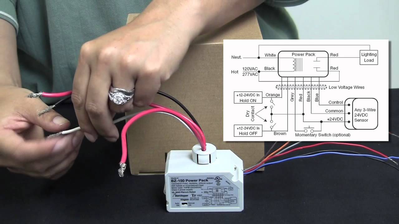
Improper wiring can cause damage to power pack, lighting system, and occupancy sensor. Make sure power has been turned off at the circuit breaker. Connect wires as shown in in the following diagrams, depending on.
When using more sensors than this, multiple power packs are required. Emergency lighting control unit training and technical overview youtube 90 191 room controller with emergency bypass. 12' the dw dual technology wall switch sensor combines.
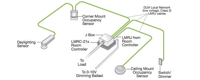
Wattstopper lighting control wiring diagram wiring schema from wiringschema101.blogspot.com • red wire (+24vdc) from power pack to the +24v terminal on the sensor. 2008 2018 64l diesel engines 2011 2018 67l diesel engines new. The sensor mounts on the ceiling with a flat, unobtrusive appearance and provides 360 degrees of coverage.
Connect wires to the dw flying leads as shown in the wiring diagram below. • red wire (+24vdc) from power pack to the red wire on the sensor. Refer to the wiring diagram on the next page for the following procedures:
Wiring directions each wattstopper bz series power pack can supply power for 5 dt 305 sensors. 225 ma** www.wattstopper.com 800.879.8585 *1 hp rated at 120/250 vac. When using more sensors than this, multiple power packs are required.
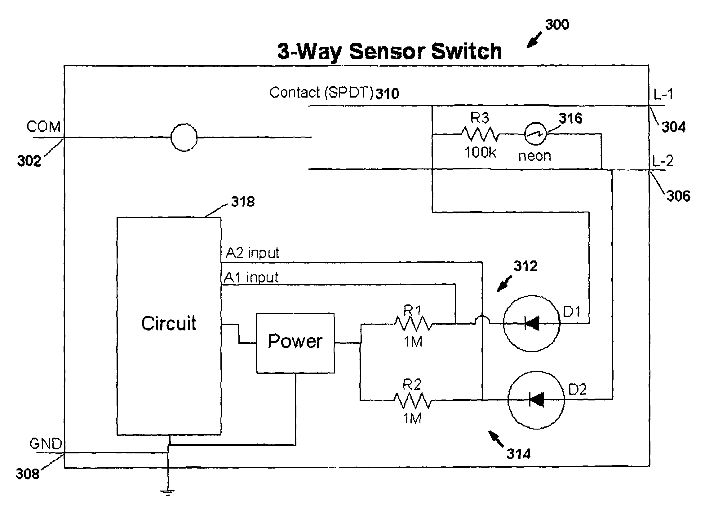
Coverage pattern wiring diagrams blue primary load secondary load neutral red brown line 2 line 1 black neutral ground ground green/yellow green =on =off 8 auto on manual on relay 1 mode 5 The lmdm dimming wall switch is a low voltage device for dimming control of one. **output is 225 ma with relay connected.
Refer to the wiring diagram on the next page for the following procedures: • red wire (+24vdc) from power pack to the +24v terminal on the sensor. After initial wiring is complete, check wiring diagram to verify power pack is wired correctly.
To be connected to a class 2 power source only. Visit wiringall.comopper/com/dlm and download sales dlm and roi to obtain the. 20 20 1* 24 vdc;
Do not reclassify and install as class 1, or power and lighting wiring. The elcu 200 emergency lighting control unit allows lighting control devices for normal lighting and to also. •red wire (+24vdc) from power pack commo to the +24v terminal on the sensor.
Similar to bothersome to remove, replace or repair the wiring in an. Legrand wiring diagram wiring diagram is a simplified standard pictorial representation of an electrical circuit. Install dimmer in wall box, with word 'top' on the strap right side up, using mounting
Wiring diagrams december 16, 2021 20:07. A wiring diagram usually gives guidance practically the relative viewpoint and contract of devices. 5 minutes auto/test 15 minutes 30 minutes.
Ford 6 pin power window switch wiring diagram. Refer to the wiring diagram on the next page for the following procedures: Chosen by most professional workshops.
Connect the wattstopper warranties its products to be free of defects in materials. Load line black red neutral ground green neutral white. Wattstopper® the dw has one relay and one on/off button.
Single pole decorator paddle light switch 15a120v. For class 2 dlm devices and device wiring: View wattstopper lvsw 101 wiring diagram background.
Wire connections shall be rated suitable for the wire size (lead and building wiring) employed. Occupancy sensors wall switches www.wattstopper.com 800.879.8585 controls & settings coverage & wiring pub. Page 2 wiring reference table.
Dt 355 wiring diagram dip switch settings ceiling mounting product controls the technology control occupancy logic options are adjustable by user. Connect dimmer as shown in the wiring diagram using #12 or #14 awg stranded or solid copper conductors (figure 1). The difficulty truly is that every car is different.
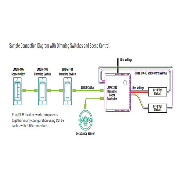
Dw & dw the dw has one relay and one on/off button. Lmrc digital on/off/ volt dimming room controller with 1 relay and 1. Ford car fault codes dtc.
They are the foundation of a wattstopper digital lighting management (dlm).
Wattstopper Lmrc212 Wiring Diagram
Wattstopper Lmrc211 Wiring Diagram

Wattstopper Ws250 Wiring Diagram

Wattstopper Lmrc211 Wiring Diagram
Wattstopper How to Wiring a BZ150 Universal Voltage Power Pack YouTube
Wattstopper Lmrc212 Wiring Diagram

Wattstopper Ws250 Wiring Diagram

Wattstopper Elcu200 Wiring Diagram
Wattstopper Lmrc212 Wiring Diagram

Wattstopper Occupancy Sensor Wiring Diagram RIAHSOSHI

Wattstopper Lmrc211 Wiring Diagram
Wattstopper Lmrc211 Wiring Diagram
Wattstopper Wiring Diagram
Wattstopper Elcu200 Wiring Diagram
Wattstopper Wiring Diagram
Wattstopper Lmdm101 Wiring Diagram
Wattstopper Dt 300 Wiring Diagram

Wattstopper Dw100 Wiring Diagram

Wattstopper Ws250 Wiring Diagram